3 Color Spot Labels

The Overview
After creating my actual brand name, Flourish Fertilizer, designing the logo, choosing typography, and getting it approved by my professor I was able to begin the first of five projects that I will complete this semester using the given resources. (refer to the “Brand Design” page for a more detailed explanation of this process)
The first project was to create a 3 color label on sticker paper that made sense to your brand. Personally, I chose to create the backside label of the fertilizer bottle for this project. I chose to design the back label because of the 3 color and Comco press restrictions. By restrictions I mean that the press I am using is fairly simple in print ability and obviously my colors are limited to orange, green, and black. It made sense to design a back side label for this assignment since those tend to be less flashy and intricate compared to front side labels of products.
I designed the label in Adobe Illustrator and then printed several proofs until it was perfect using the feedback and guidance from both of my TAs and professor.
Design, Proofing, & Preflighting
To begin the process of creating the labels I started with a sketch. The image to the right is a rough sketch of the label for the backside of the fertilizer bottle. This sketch was completed on an iPad using Procreate.
The Comco Press that was used to create the 3 color spot labels has a finishing side to the press. The finishing side die-cuts the label paper in order to create the desired shape. In order to have time for each student to print, we were given “color partners” or another student who was also assigned the same colors. Therefore we chose the die shape together for something that would work for each of our products. The shape my partner and I chose to work with was a rounded rectangle that measured 4 by 2.875 inches. In Illustrator I designed the label based off of my sketch to fit inside the die lines of the specific die measurements we chose.
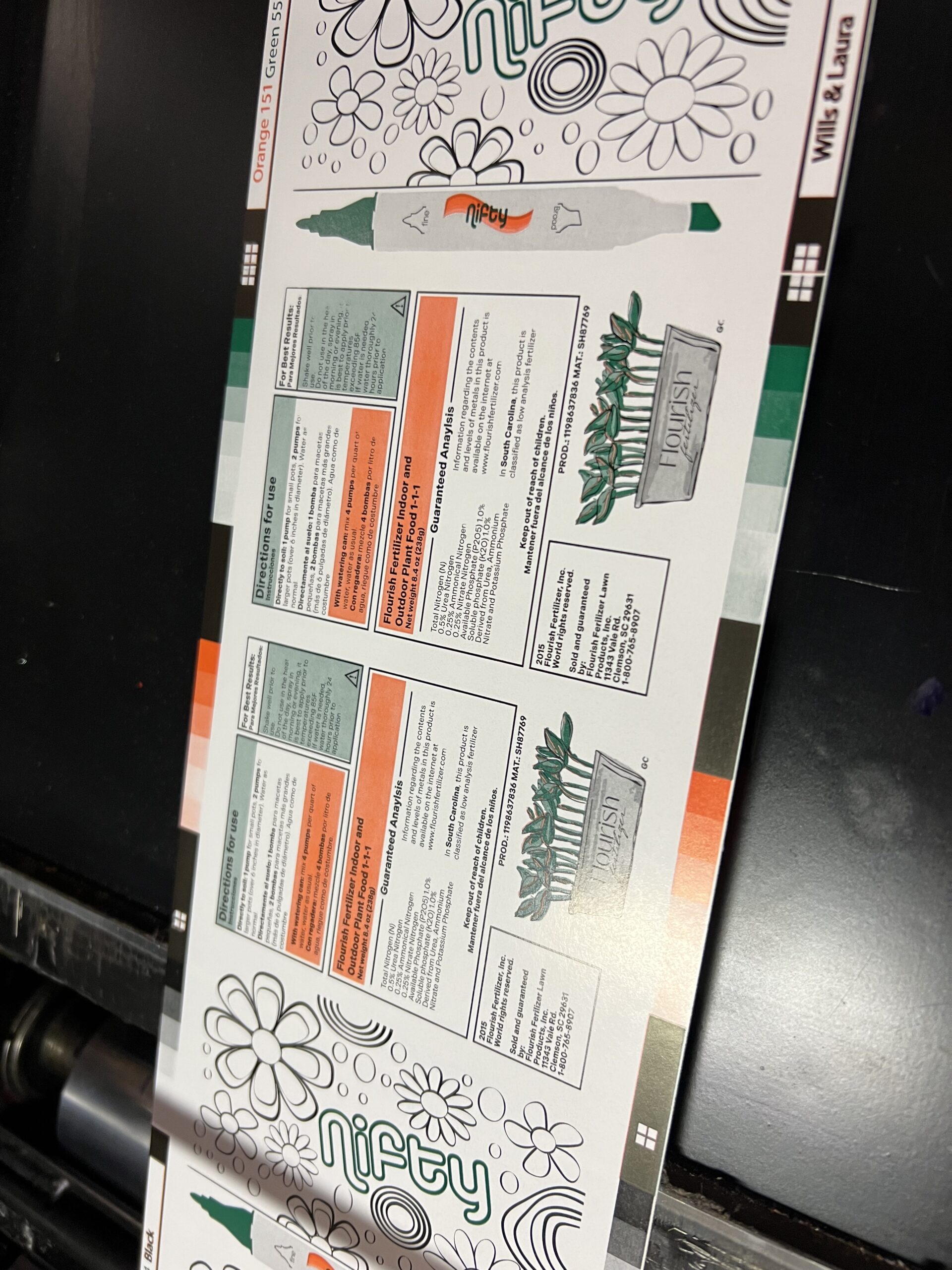
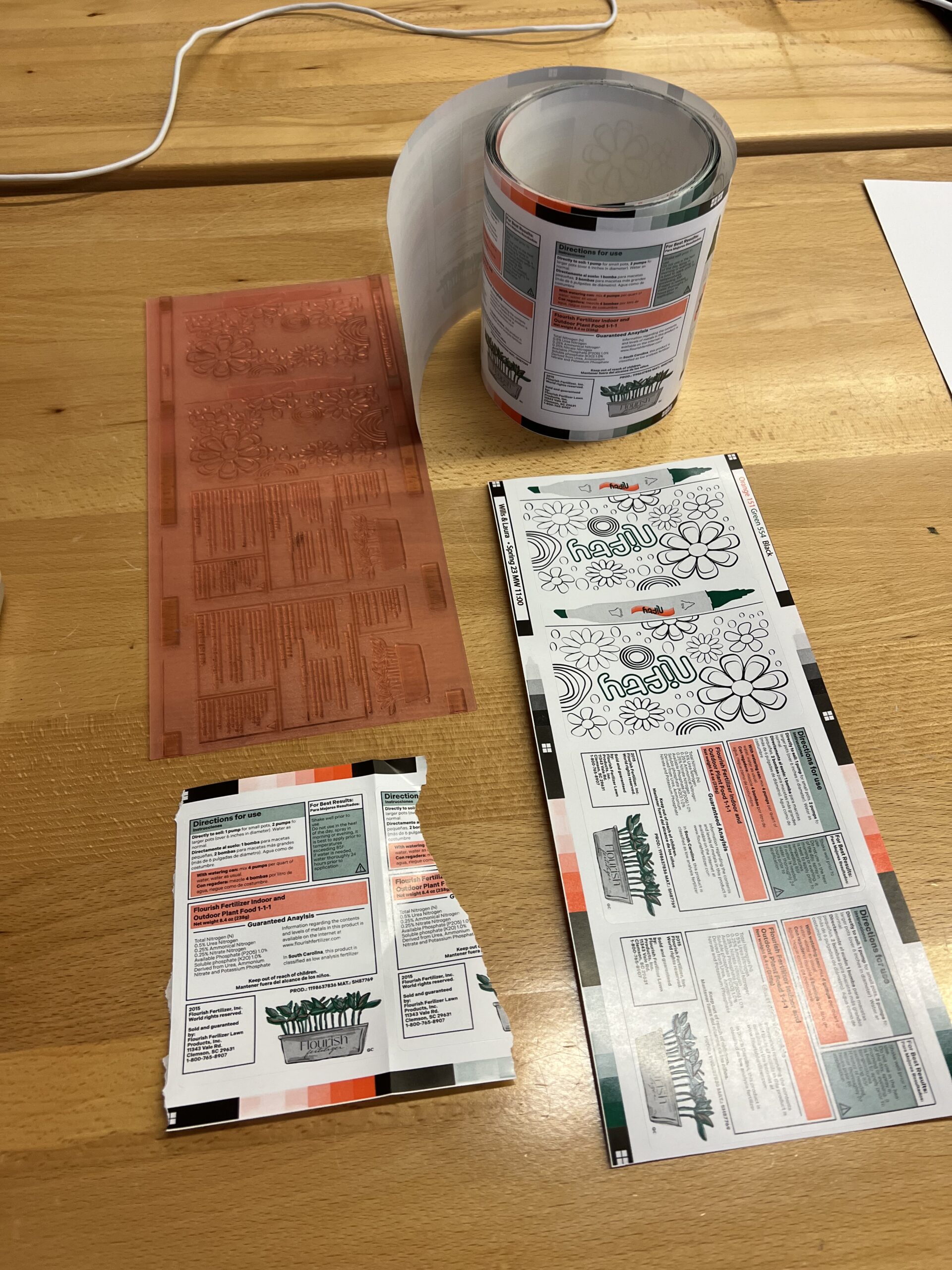
The digital design of the label from illustrator can be seen here also.


After designing the label contents there was the addition of bearer bars onto the file. Bearer bars are a registration tool that the press operator uses when printing multiple colors on top of one another. The bearer bars also hold the color call outs as well as the names of the students who’s print it is. After the digital design, the next step is a physical proof.
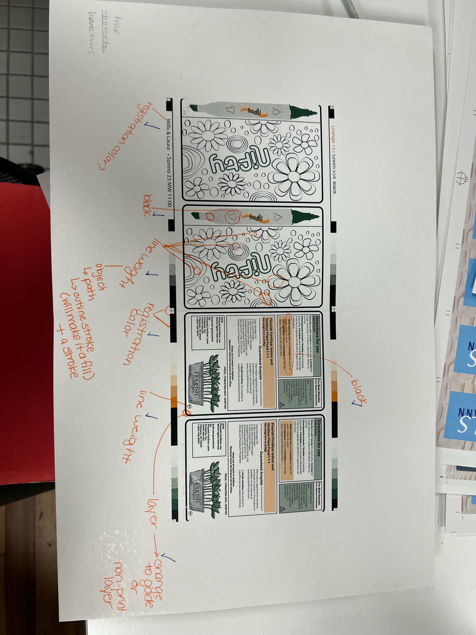
The image to the right is a physical proof I printed using the Konica Minolta. The proof was then reviewed by my professor many times shown by the writing on the actual paper. My professor’s comments included things like making sure the bearer bars were in registration color and spot colors, checking the separations, determining the LPI, and making sure the font of the label was going to be legible by referencing the test targets printed earlier in lab.
A big concern at this step was how small some of the type was on the label. To fix this, I made the font sizes all slightly larger and knew that I was going to have to be very precise on the actual press to get the crisp small font printed.

Next the application ArtPro+ is used to alter the file before it is finally ready to use when actually make plates. In ArtPro+ the file is turned into each color plate separately when launched. For example, in this case the file was turned into an orange plate, a green plate, and a black plate. In ArtPro+, we also defined our LPI of 150.0 ruling as well as the angle for each separation of color. Once completed in ArtPro+ the file is launched to the Graphic Communications server in the building which allows us to retrieve files between our personal computers and the lab computers.

After all of the proofing and work in ArtPro+, it was time to begin making the photopolymer plates that would later be mounted onto the Comco press to print the label.
Photopolymer Plate Making
The photopolymer platemaking begins by retrieving a piece of DFR .067 mil photopolymer (30 inches) from the platemaking room. The plates are stored in cardboard boxes which are very important to close properly after getting your plate. After the retrieval of the photopolymer, it is time to back expose it. The exposure unit used is the Cyrel Unit which can be seen here. When back exposing we placed the glossy side of the plate face up in the Cyrel Exposure unit. The plate gets exposed for 85 seconds and then once it finishes, flip over the plate and place it on top of the imager as a flat surface. After that, it is important to quickly rip off the film layer all at once in one fluid motion.


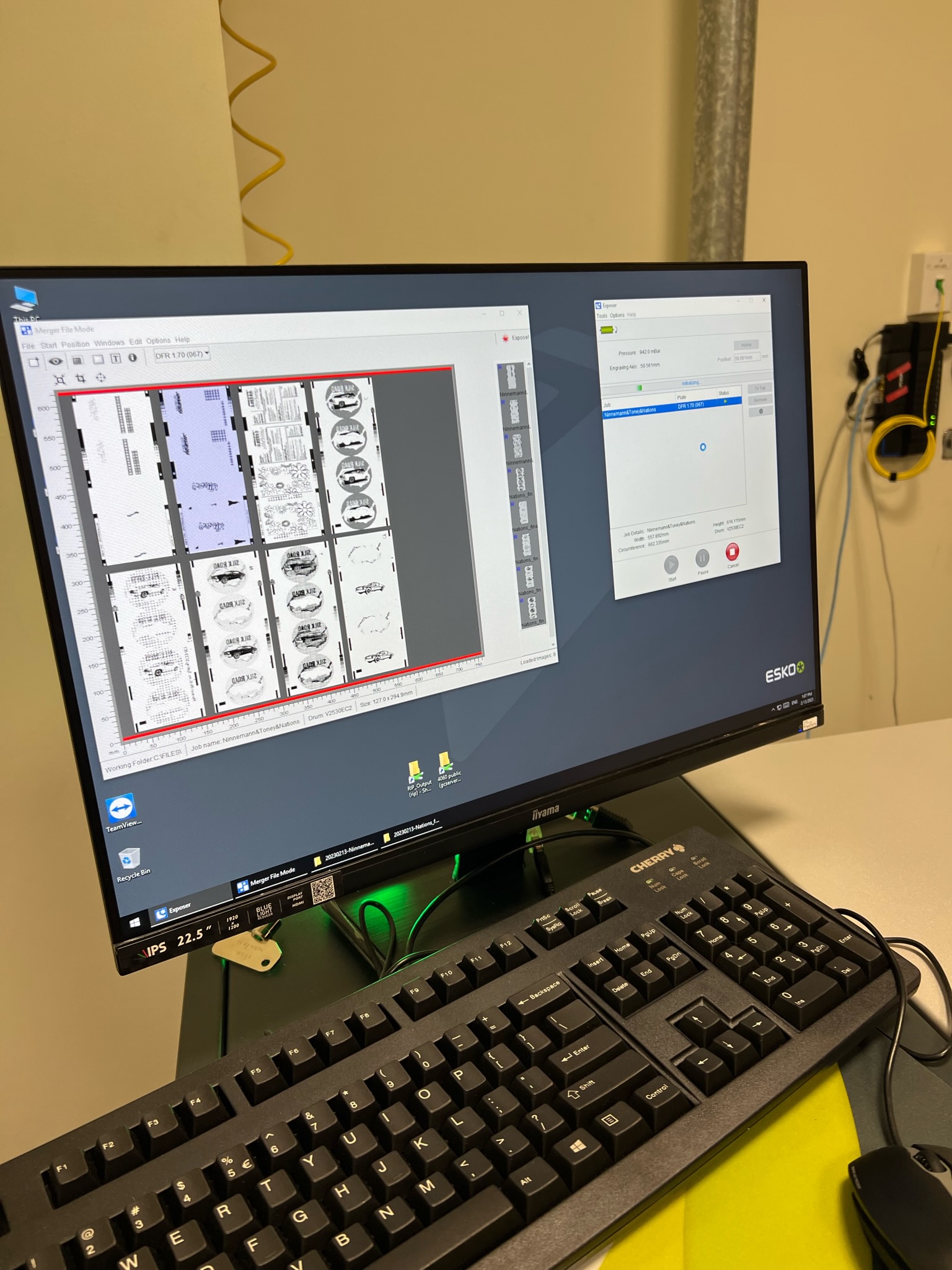
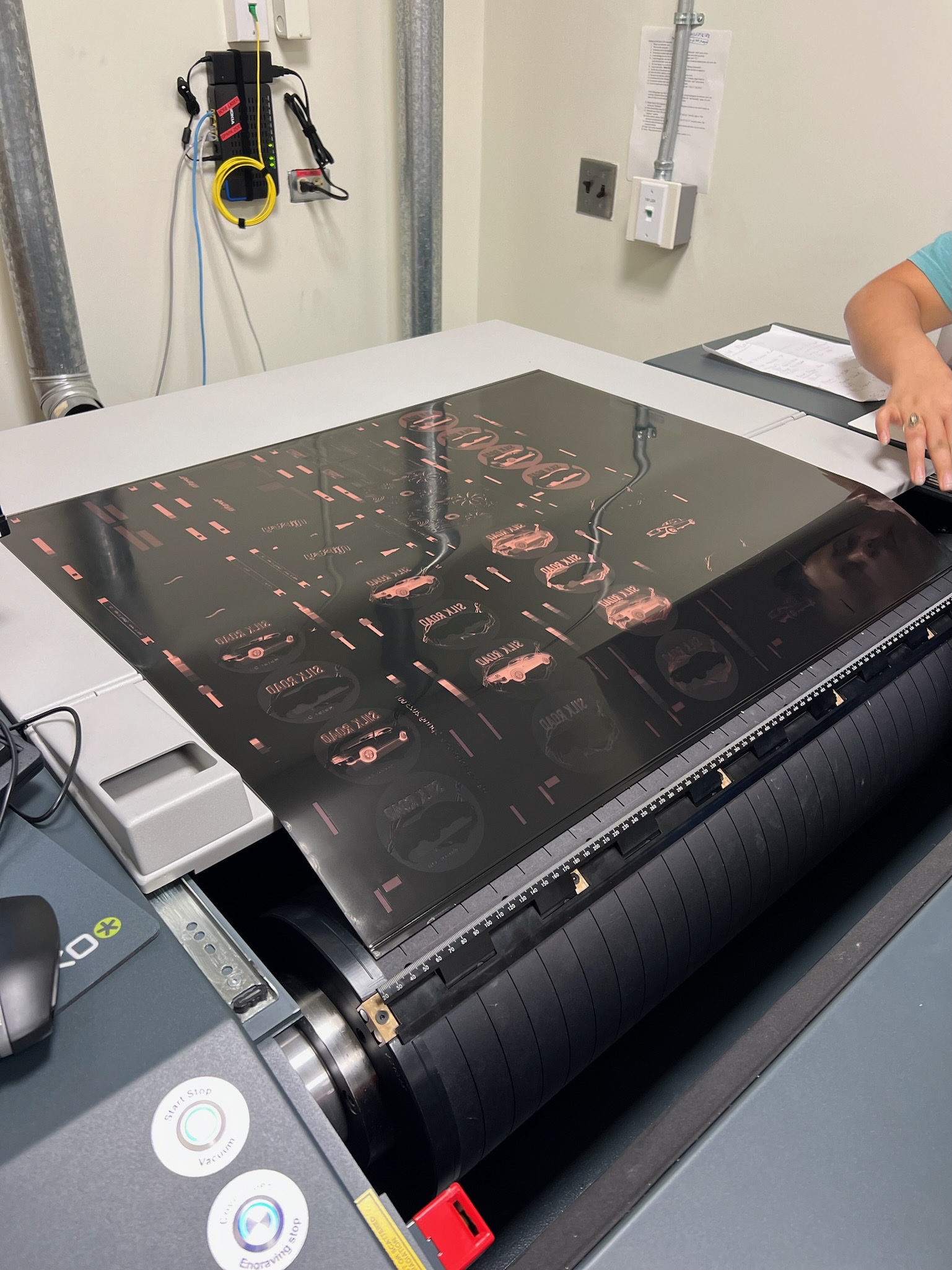
After that it is time to insert the plate into the Esko Part 2350 Carbon Copy Laser Engraving “Imager” Unit. On the computer attached, we chose the files we launched to the server and placed them in the merge folder. The size to select is DFR067 which corresponds to the plate material we are using. There will be a file to drag onto the live are for each color you are printing (I had three) and it is important to check the LPIs of each. This can be seen by the image on the right. These LPIs matched what I set in ArtPro+ therefore I could proceed. Next we loaded the plate into the imager, hit the open cover button and then position the plate at the ruler of the drum on the bottom at 30 mm. Use the wrench to loosen and tighten the plate in place. Then turn the vacuum and wrap the plate around the drum. Once all the way around use the wrench to lock it on the other side, this part of the process can be seen in the left image. Next, close the cover all the way. After the plate is securely on the drum double check to make sure all of the plates are lined up in-between the red bars or live area on the computer software. If everything is secure at this point, hit start, hit ok, and then a green light appears which lets you know the process has begun. This takes about 30 minutes to image.

After the imager, the plate goes back into the exposure unit for a basis exposure. The plate is laid on the exposure unit face up as the top feels rubbery. Basis exposure is 6 minutes long to harden the face, this exposure makes the carbon copy hard so it will not wash away later on in the process.

After that it is time to move to the processor. The processor we use is the 1,000 TD Thermal Developer, which is known as the thermal washout. Place the plate face up into the processor, open the clamps, and slide the plate under them. Make sure the plate corners are under a clamp! After the plate is secure, use the screen of the processor to select DFR067, the kind of plate, 10 revolutions, the amount of times it will spin around, and a width of 30 inches, the size of the plate. Once you review all of the choices made on the screen, hit enter. This thermal processing takes about 12 minutes.

After this, take the plate back into the exposure unit for one final time. The plate is placed in the first drawer of the machine this time rather than the top of the machine. Make sure to hit the #2 and #3 buttons at once. This final exposure make the plate not tacky anymore.
After the actual plate making is complete, it is time to slice the plates apart from each other. It is important to use the slicing tool rather than scissors. Make sure you do a rough cut, and then use the guillotine cutter to slice even closer to the bearer bars vertically on the plate. The last cut will be off of the horizontal end of each plate. Make a slight chop off of the horizontal edge of the bearer bars in order to allow for ease of mounting later on. Taking off a slight bit of the actual bearer bars allows for the plate to match up perfectly rather than overlapping slightly when wrapped around the cylinder.


Plate Mounting
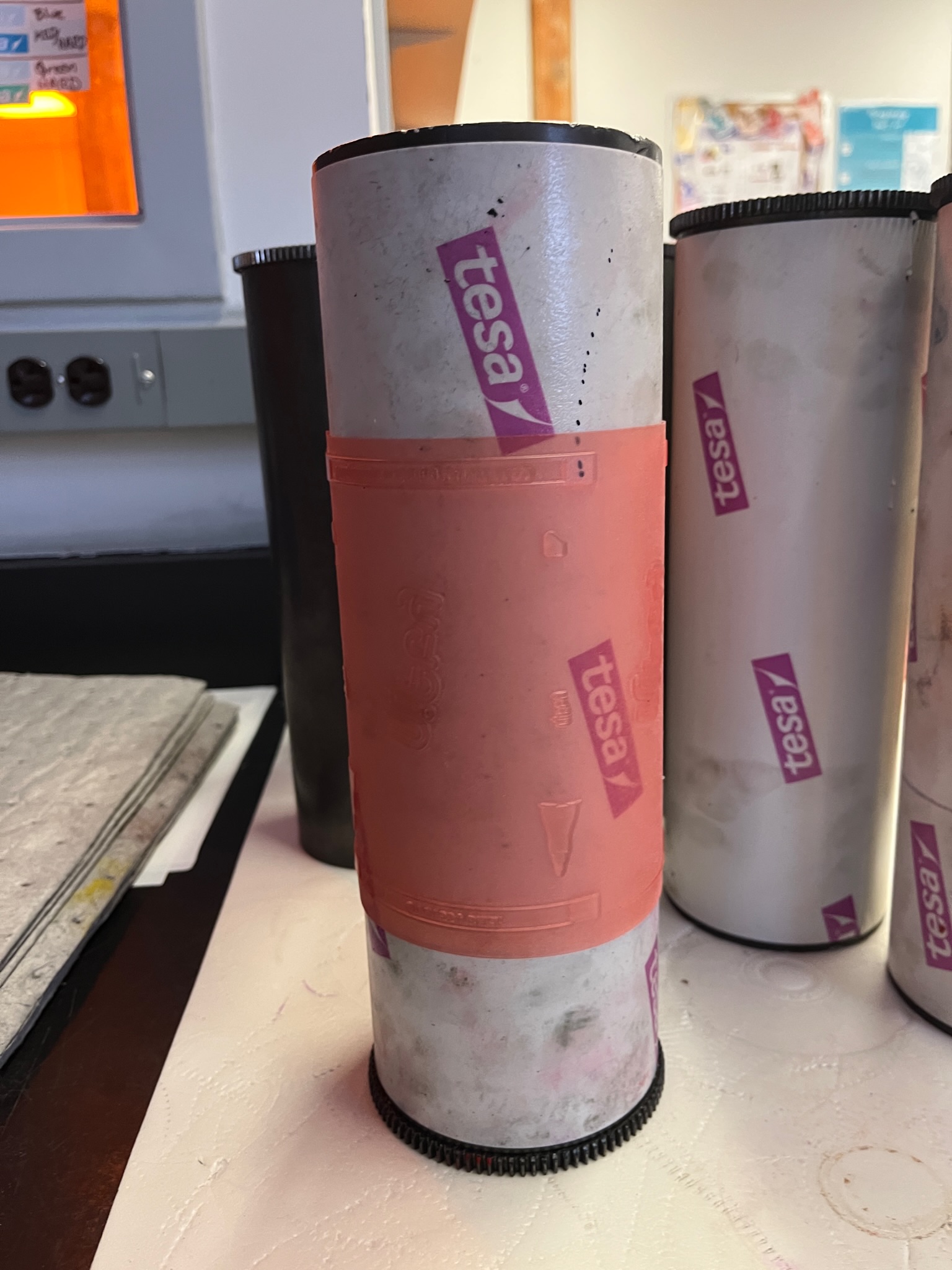
Once the plates were cut correctly, the mounting process can begin. We used the machine pictured to the left along with a plate cylinder. The plate cylinder is mounted into this machine with the gear side to the right and the operator side to the left. After that is mounted, we then took the photopolymer plates and began lining up the registration marks in the bearer bars with the cross hair lines on the computer monitor seen here. This step is crucial to having good registration on press, and really helped us get perfectly aligned coloring when we got to the actual press. I truly think the detail and time we spent in this step of the process really helped our final printed labels look great.

Comco Press Set Up

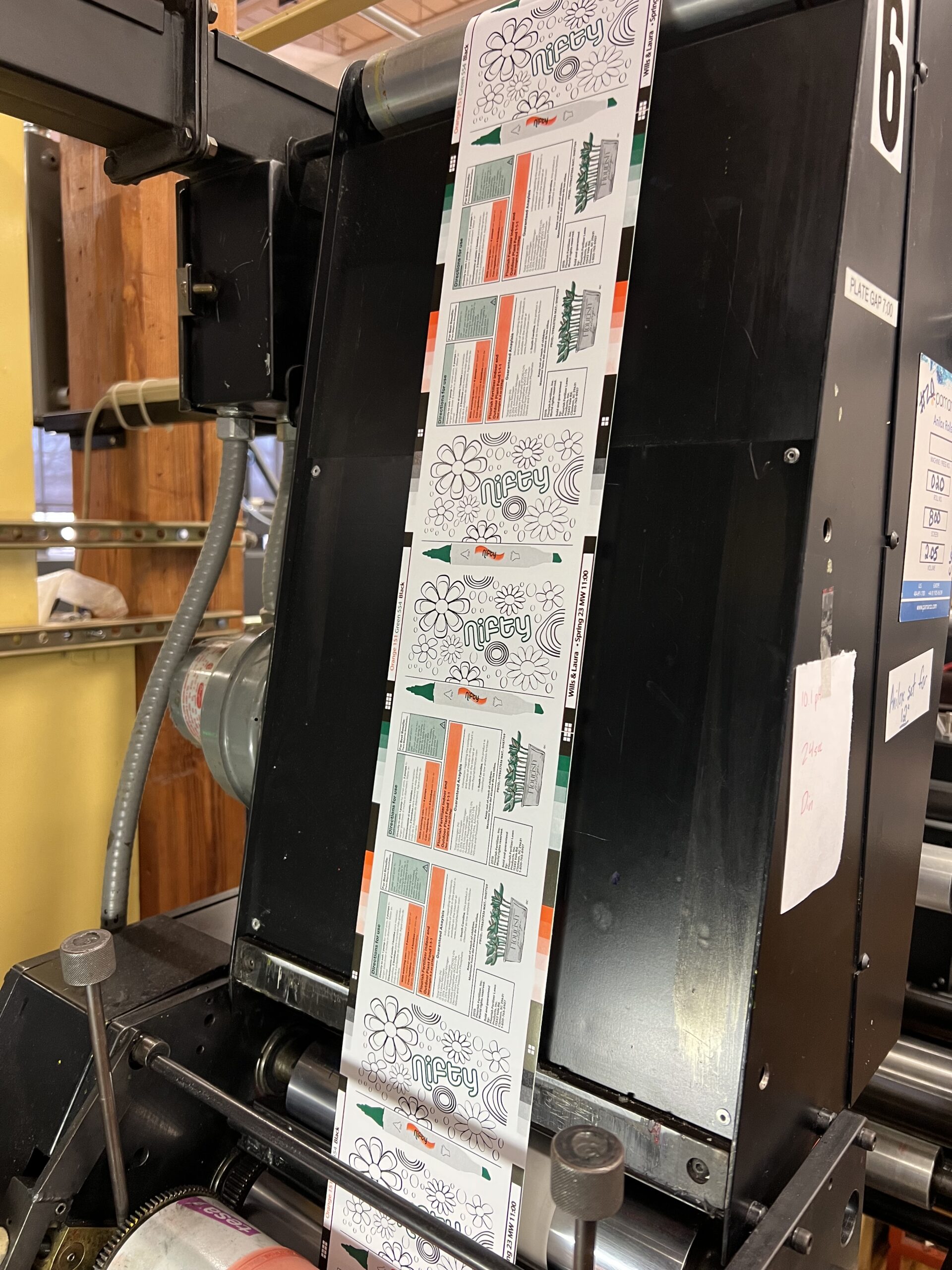
The substrate that was already installed on the Comco press is called Mactac Permanent RDT21153 60# FSG SCR 1869984 (shown in the image to the left). This substrate is a sticker paper that is 5 inchs wide by 5000 feet long and it mounted on the input side of the press. The die line that was chosen specifically for my label earlier in the process (shown in the image to the right) was also mounted onto the output end of the press, this will allow the stickers to be cut into rectangles before even taking them off of the press.

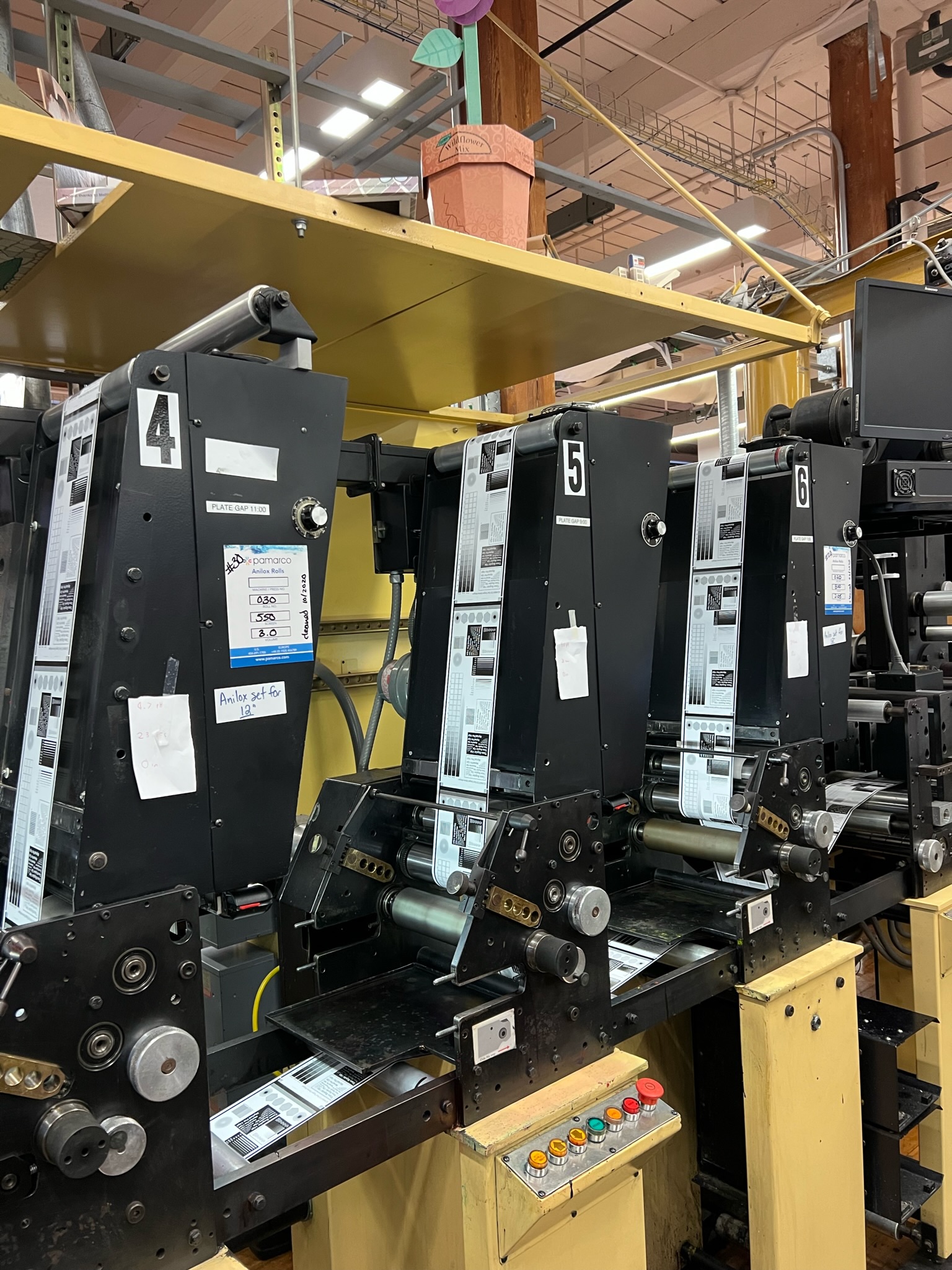
Once the plates are mounted, it is finally time to move to the actual Comco press and get to printing! Since we were using three colors, orange, green, and black, we have to set up three stations of the press. Each station on the press corresponds with a set of drawers that has every tool and piece of equipment needed to set it up.
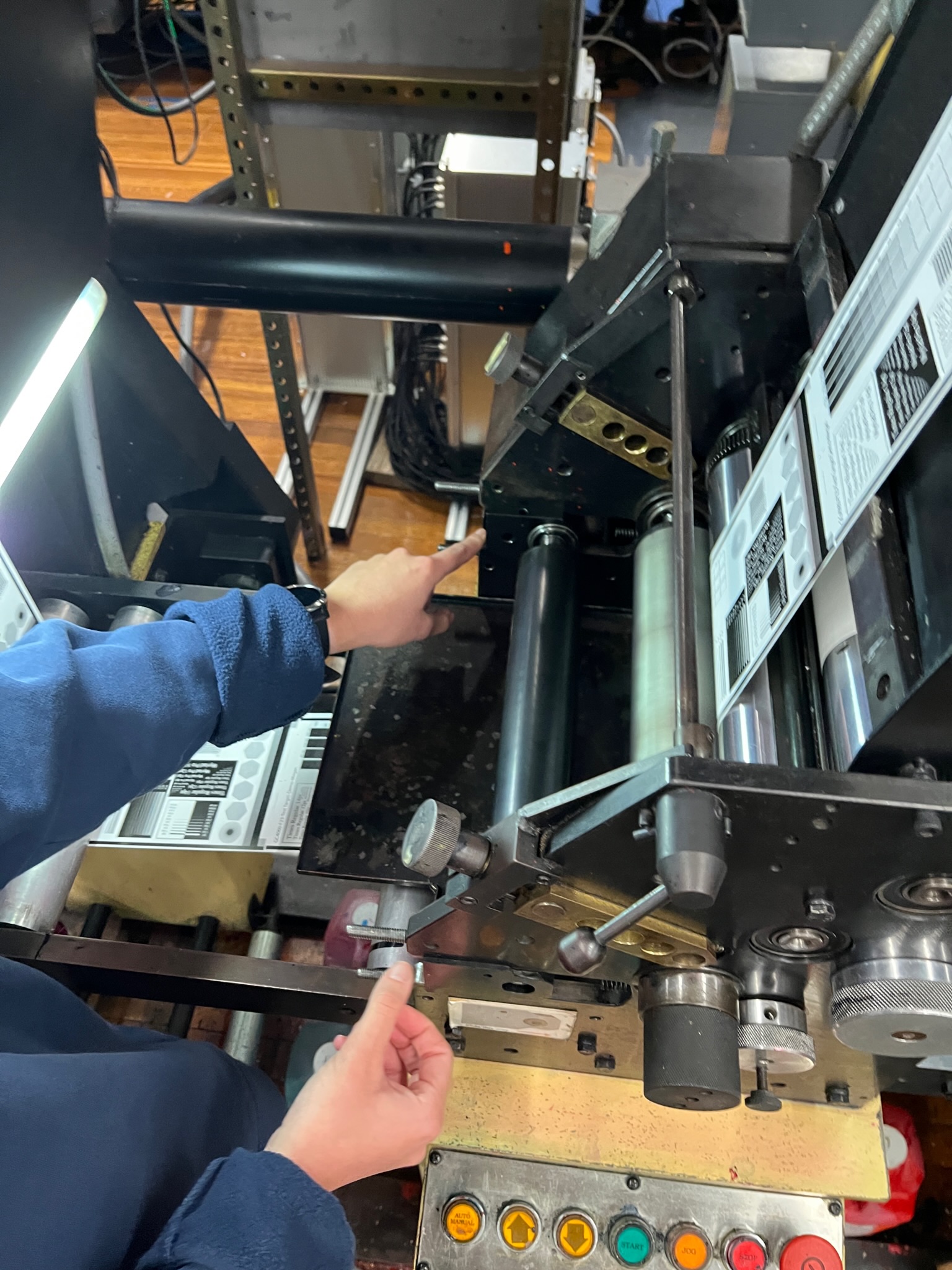
The photo in the middle is a completely empty section of the press before any set up has been done. The photo to the far right is a completely set up section. Each section is the same set up, with the obvious change of ink color, and now we will take a deeper look into setting up the press.


The first step in setting up a section is to look in the top drawer that contains sharps, gloves, and a rubber roll (or ink metering roll). Place the roll with “super man’s cape” behind you. Then place the roll into the machine parallel with the gear side far away from you. Make sure to keep a pinky’s width between the end of the machine and superman’s cape on both sides. Next put on the gloves and locate the second drawer. This drawer has the doctor blade, 2 s clamps, and 4 s clamp bolts. Hold the doctor bade carefully and flip it away from you so if you fall you will not get hurt. Place the doctor blade into the pinky gap we left earlier. You can now take off the gloves.


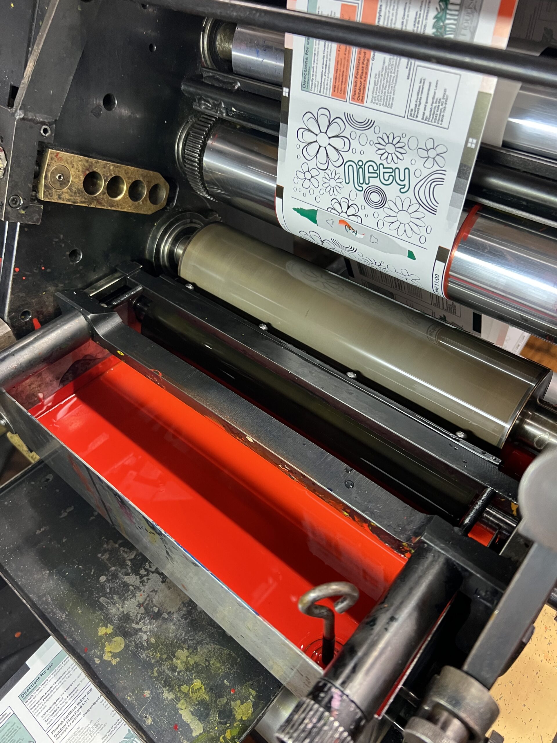
Next, place the S clamps loosely on the machine and then place on two clamp bolts with no extra pressure. Make sure things stay loose so everything in the press stays parallel. After that, take both major S clamp screws and turn them clockwise at the same time. Allow for an eight of an inch between the rubber roll and the anilox roll. Locate the ink tray and place it cupped around the ink metering roll in the machine After that is in place, feed the ink rods through the tray and into the machine. A very important next step is to make sure you place the ink tray plug into the ink tray! We do not want ink pouring out onto the floor. To reenforce this, place a blue wipe from the top drawer into the ink tray hole on the outside so it won’t even drip a little bit. Now, grab the ink jug of your color and begin to swirl it around. Do not shake the jug because that will create bubbles and those will alter the viscosity readings of the ink. Pour the ink into the tray until it hits the bottom of the ink metering roll.

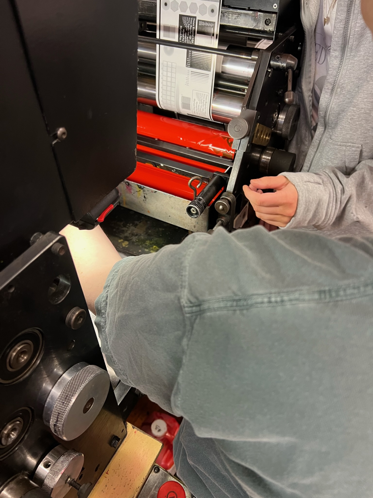
Now it is time to move the ink metering roll forward so that it is touching the anilox roll. You are looking for the pattern of a soup can to appear in the ink. Metering the ink in this case is very important, to ensure that only the correct amount of ink is transferred from the anilox roller to the plate. After you achieve the soup can look, call over your professor before the next step. Once supervised, move the doctor blade counterclockwise until there is no longer the soup can look, and less ink on the roll.

Next look in the third drawer to find the plate rod and plate clamp. Make sure the adjustment knob shows up in the middle of the plate rod rectangle, as well as notice the non-centered circle that we look at later on. Make sure the machine is off at this point to stay safe. Next put the rod into the plate cylinder with the mounted photopolymer plate on it, and make sure the gear side is away from you as you slide it into the machine. Place the plate rod in the third hole on the side of the machine in the gold section. Keep your finger on the plate rod so it doesn’t fall off, and place them vertically onto the plate rod into the machine and twist to clasp it. The press won’t drive unless these gears are interlocked. Now the basic set up of the press and its various pieces are in place.

Complete the previous press set up steps for each section of ink you are using. For me, I completed setting up a section on the Comco press for black, orange, and green ink. Once this is complete, the press as a whole is fully ready for the actual run.
Running the Comco
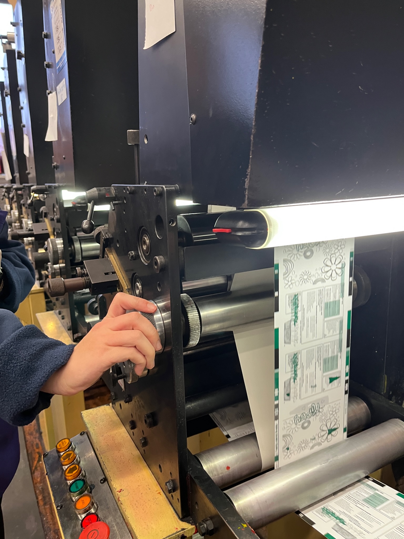
After setting up the sections on the press, you have to say “clear” and then hit start on the press. Once the press is running, the next step is setting the impression. To do this, move the plate knobs clockwise. Make sure to do this slowly so if something goes wrong you won’t over impress too quickly. This is plate to substrate impression. After that, you will create anilox roll to plate impression by adjusting the anilox roll knobs. This however, is very rare to have to do, you shouldn’t have to do this much! We want the least amount of pressure on the machine overall.


The registration of the plates is also altered at this point. As you can see from the left image, the orange layer of ink is not aligned correctly. To fix this, rotate the knobs on the machine until it is lined up perfectly. The image to the right is a computer monitor connected to the Comco press. This monitor allows you to achieve even better registration because it allows for a magnified view of how the colors are printing on one another.

To achieve perfect registration with all three colors we were using was difficult, but we were able to achieve really strong registration in the end. I attribute our exact registration to how well we were able to mount the plates earlier in the process, as well as taking our time when registering the machine while it was printing.

Once the set up, impression, and registration were all completed correctly, we just let the press run for a moment to allow it to print off a large number of labels for my fertilizer bottles! I am thrilled with how the labels turned out. I think that I digitally designed the label with this press run in mind which is how I was able to achieve such a clear, clean, and effective design of the label. The second attribute to the success of the label printing was how thorough and attentive I was in the plate making process as well as the press set up. I took my time doing each next step with the intention of checking my work to make sure the printed product at the end would be successful. I can confidently say that I am proud of the final label that I printed on the Comco press!

Comco Press Cleaning
The cleaning process of the press is very important to complete accurately and with the right tools to keep all of the equipment and parts in good shape for other students to use. Each piece we are using here is very expensive and the cleaning process is important to keep the life of each piece. The cleaning begins with the removal of the plate cylinder and rod. The plate is then simply peeled off of the cylinder and can be thrown away or washed off. The following step is one that needs to be done very carefully. Since we poured a lot of ink into the ink tray, we need to save the excess ink we didn’t use. To do this, carefully take an ink funnel and place it into the ink jug. Then place the funnel under the ink tray opening on the bottom that has the blue tissue in it. Once that is secure, slowly remove the tissue as well as the ink plug. Let the excess ink run back into the jug. Once this is done, simply place the ink plug back in the hole and then take the funnel to the sink. Next, spray the anilox roll down with water to remove all of the excess ink. After that, you can spray the anilox roll with the cleaning solution to get everything cleaned completely. After that, carefully remove the ink tray rods as well as the ink tray and take it to the sink where you can clean everything with water. Lastly, remove all of the remaining pieces from the press section and place them back into the correct drawers. Be especially careful when handling the doctor blade as always. That completes the clean up of the Comco press.
The Final Product
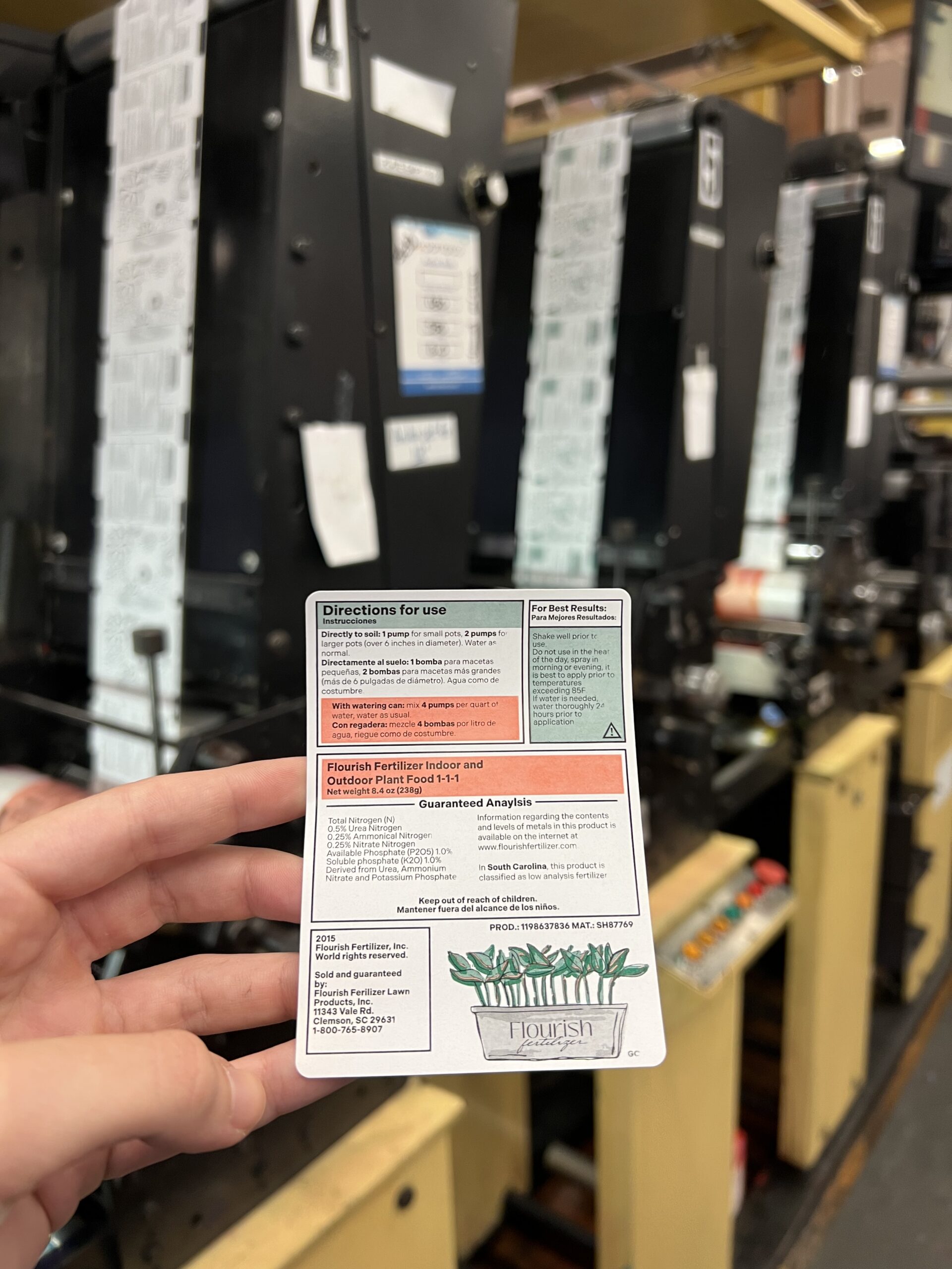
This here shows final sample taken from the Comco press. My three color label was extremely successful through and through. I think if I could have changed anything from the process I would have been more familiar with the preflight process in ArtPro+, since that area I needed a lot of assistance in. Other than that, I think that I was well educated and well equipped to be successful in this assignment and that showed in the final product for sure.
Hit “play” on the video to see the process on press!
Use the left and right arrows to scroll through some images of the process!